Digital uP Card CP16
The card implements a standard uP system using the Phillips 80C592 running at 15Mhz. Eight analog inputs with optional input filters and amplification are provided. The card can close a PID loop with an analog device (such as a DC motor) by using the analog inputs and the PWM output lines. The additional "amplifier card" must be used if the device draws excessive power.
Specifications
- 80C592@15Mhz CPU.
- Up to 64KiB program memory in standard EPROM
- 256 bytes internal, 2048 bytes external RAM
- 8 analog inputs with optional low/high-pass filter and applification.
- 2 PWM outputs.
- Selectable address with 4-bit switch.
- RS-232 output
- Watchdog timer (selectable with jumper).
- ISA type slot connector.
Requirements
- Power supply input 12V DC or 5V DC (selectable with jumper).
Design
The CPU is coupled together with an external EPROM and RAM. Using external RAM we can use a "Large" memory model during software development, giving us more memory space for storing program variables. The serial port is also implemented, allowing debug messages to be examined. The MAX232 chip is used for voltage conversion from TTL to RS232 compatible signals. The BUS is implemented using the ports P1 (LSB) and P4 (MSB). These ports have "open-drain" outputs with internal "pull-up" resistors, also known as "quasi-bidirectional" ports. This way one single line can be used as an input and an output at the same time.
Each card has a unique 4-bit ID that is selectable with an onboard switch. This ID is logically compared (using logical gates) with lines P4.3, P4.4, P4.5 and P4.6. If they are identical and if P4.7 is low then the External interrupt of the 80C592 is triggered, informing the CPU that it should perform some action on the bus. More information on this subject is available under the "Bus Communication" section.Eight analog inputs with optional input filters and amplification are provided. Amplification is enabled or disabled using jumpers JP0 to JP7. Input filters are optional but in case that they are not used Ax must be short-circuited and Bx must be left open. Many amplification scenarios can be implemented by choosing the appropriate resistors and capacitors for Cx, Dx, Ex and Fx. Variable resistor TRx should be used to balance the operational amplifier LM324. The board can be power directly from 5V DC or the onboard 5V regulator can be used to convert the input voltage (8 - 19V) to 5V DC. Jumper JP12 must be used for the selection.
Board
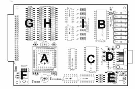
- CPU
- EPROM (maximum 64KiB)
- RAM, 2KiB (6116)
- RS-232 Serial port
- Board ID selector
- Input voltage level (set jumper to 1-2 if input voltage is 5V, and to 2-3 is input voltage is in the range of 8-19V)
- Input low/high pass filter
- Amplifier components
- Amplifier selector (set jumper to 1-2 for no amplification, 2-3 for amplification)
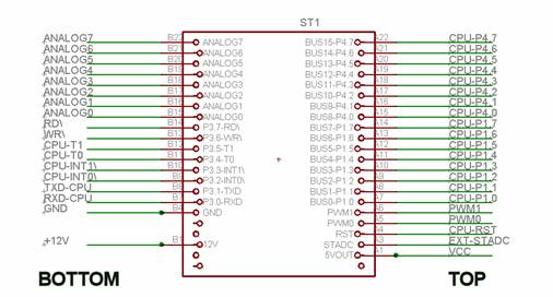
Board ISA connector
Bus Communication
The communication protocol is implemented as follows (this implementation can be changed in the future to allow direct peer to peer exchange of data without the use of a "master" card). One card is chosen to play the role of the "master". Data can only be exchanged between the "master" and any of the other cards (called "slaves"). Only the master can initiate a data transfer. The master can command a card to read data from the bus or to write data to the bus. The protocol requires that the "master" has a device ID = 0000.
Bus description
The 16-bit bus is described in the following table :
P4 |
P1 |
||||||||||||||
7 |
6 |
5 |
4 |
3 |
2 |
1 |
0 |
7 |
6 |
5 |
4 |
3 |
2 |
1 |
0 |
INT\ |
A3 |
A2 |
A1 |
A0 |
R/W\ |
P |
H/L\ |
V7 |
V6 |
V5 |
V4 |
V3 |
V2 |
V1 |
V0 |
INT\ : Interrupt request (negative logic, hardwired). When this bit is set to zero the slave machine selected with bus lines A0-A3 is interrupted. The interrupt service routine (ISR) on the slave machine is activated and performs an 8 bit read or write according to the rest of the P4 control lines.
A3-A0 : Slave address, hardwired.
R/W\ : Read or Write\. A set bit (1) indicates a master read (data transfer from slave to the master, see "Data read") and a zero bit (0) indicates a master write (data transfer from master to the slave, see "Data write").
P : Parity bit. Used to perform error correction on the data transmission. An even parity is used. The parity bit is calculated for the 9 bit word : [HL\, V7, V6, V5, V4, V3, V2, V1, V0].
H/L\ : High or Low\ byte. Used to enable 16 bit data transmission. This bit indicates if the data in P1 refers to the High or Low byte of the transmission.
V0-V7 : Data bus.
Data Write (master writes data to slave - RW\ = 0)
The master can send 16bits of data to any of the slaves using a double write on the bus. First byte to write must always be the LSB. The procedure to write a single byte is described in the following table :
MASTER |
SLAVE |
BUS |
Start byte transmission |
Running PID loop |
P4 = 0xFF, P1 = 0xFF |
Set slave address |
Running PID loop |
P4 = 1 | A3 | A2 | A1 | A0 | R/W | P | H/L |
Set High or Low byte |
Running PID loop |
P4 = 1 | A3 | A2 | A1 | A0 | R/W | P | H/L |
Trigger IRQ |
Running PID loop |
P4 = 0 | A3 | A2 | A1 | A0 | 0 | P | H/L |
Wait for 64us (safe period) |
ISR activated |
|
|
Read data from bus |
|
|
Perform error check |
|
|
Discard 16 bit word on error |
|
|
Place byte in 16 bit word |
|
|
Interrupt return (IRET) |
|
Reset Bus |
|
P4 = 0xFF, P1 = 0xFF |
Data Read (master reads data from slave - RW\ = 1)
The master can read 16bits of data from any of the slaves using a double read on the bus. First byte to read must always be the LSB. The procedure to read a single byte is described in the following table :
MASTER |
SLAVE |
BUS |
Start byte reception |
Running PID loop |
P4 = 0xFF, P1 = 0xFF |
Set slave address |
Running PID loop |
P4 = 1 | A3 | A2 | A1 | A0 | R/W | P | H/L |
Set High or Low byte |
Running PID loop |
P4 = 1 | A3 | A2 | A1 | A0 | R/W | P | H/L |
Set Read mode |
Running PID loop |
P4 = 1 | A3 | A2 | A1 | A0 | 1 | P | H/L |
Trigger IRQ |
Running PID loop |
P4 = 0 | A3 | A2 | A1 | A0 | 1 | P | H/L |
Wait for slave (R/W = 0) |
Everything ready, set R/W = 0 |
P4 = 0 | A3 | A2 | A1 | A0 | 0 | P | H/L |
Read data |
Wait for 64us (safe period) |
P4 = 0 | A3 | A2 | A1 | A0 | 0 | P | H/L |
Perform error check |
Wait for 64us (safe period) |
P4 = 0 | A3 | A2 | A1 | A0 | 0 | P | H/L |
Discard 16 bit word on error |
Wait for 64us (safe period) |
P4 = 0 | A3 | A2 | A1 | A0 | 0 | P | H/L |
Reset bus |
Wait for 64us (safe period) |
P4 = 1 | 1 | 1 | 1 | 1 | 0 | P | 1 |
Wait for slave (R/W = 1) |
Reset bus |
P4 = 0xFF, P1 = 0xFF |
|
Interrupt return (IRET) |
|
|
|
|
|
|
|
|
|
|
Click here to download sample code